ZYBO quickstart02. Jul '14
Introduction
Studying FPGA development is rather expensive process and so far the cheapest way to get started in my opinion is to get equipped with Digilent ZYBO development board, OV7670 camera, Salea logic analyzer, a breadboard, light emitting diodes, segment displays and some 220 ohm resistors. If you get lucky you can push it down to 200€ budget.
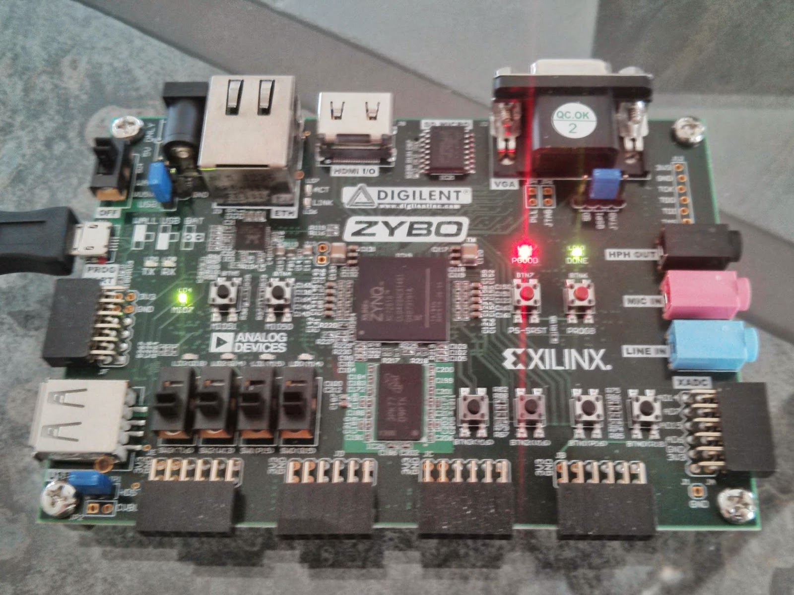
ZYBO is a Zynq-7000 SoC based board from Digilent. This is a little HOWTO for getting started with ZYBO, but this should serve well anyone who wants to get on the track with Zynq-7000 based boards such as Zedboard, Microzed, ZC702 evaluation board etc.

ZYBO is a Zynq-7000 SoC based entry level board.
Previously I attempted to outline detailed process of creating hardware design for ZYBO using Vivado, but as it turned out to consume significant amount of time spent on learning vendor specific stuff I decided to take the shortcut. Digilent provides ZYBO Base System Design 1 which includes prepared high level block design and IP cores for VGA output, HDMI output, and audio codec input/output.
As it is easier to remove useless blocks than to create block design from scratch this is recommended course of action. Base designs should be available for all Zynq-7000 boards from the corresponding hardware vendors. Otherwise you have to follow pretty complex guide to set up the high level block design from scratch 2.
Installing Vivado
Bitstream is a 2MB binary file which configures the programmable logic of ZYBO. Unfortunately the bitstream file can currently be compiled only with proprietary tools from Xilinx. When you're purchasing ZYBO from Digilent you have option to get 20 USD accessories kit for ZYBO which includes Vivado voucher. With the Voucher you get license for Vivado and it's updates for a year since the date of purchase. You can download Vivado at Xilinx web 3, just follow release notes to install Vivado and the license file Xilinx.lic. Note that license will be bound to the MAC address of the particular machine.
Working around Vivado quirks
If you encounter floating point formatting exception try disabling locales by appeding following to Vivado's settings64.sh:
export LANG=CIf you bump into NullPointerException while attempting to run Tools → Create Package and IP try to:
Open from main menu Tools → Project settings
Click on IP
Select Packager tab
Make sure Vendor field value if anything but (none)
Preparing bitstream
ZYBO Base System Design 1 includes all you need to compile the bitstream file for ZYBO. Uncompress the .zip file and open the project file source → vivado → hw → zybo_bsd → zybo_bsd.xpr with Vivado.
With newer Vivado versions you get notifications that IP blocks can be upgraded. Follow instructions on the screen to update the components. Once you have finished with the hardware design click on the lefthand panel Program and Debug → Generate Bitstream this will generate the 2MB blob that represents your FPGA configuration.
Preparing microSD card
The easiest is to use Xillinux as a starting point 4. Grab the Xillinux image and dump it to your microSD card. Note that previous contents of the card will be lost:
umount /dev/mmcblk0p*
wget -c http://xillybus.com/downloads/xillinux-1.3.img.gz
zcat xillinux-1.3.img.gz > /dev/mmcblk0
partprobe
Now you have your memory card populated with FAT32 filesystem for u-boot and ext4 filesystem which hosts Ubuntu 12.04 root filesystem. Next step is to place device tree definition file and first stage bootloader to the first (FAT32) filesystem:
wget -c http://xillybus.com/downloads/xillinux-eval-zybo-1.3v.zip
unzip xillinux-eval-zybo-1.3v.zip
mkdir /mnt/xillyboot
mount /dev/mmcblk0p1 /mnt/xillyboot
cp xillinux-eval-zybo-1.3v/bootfiles/boot.bin /mnt/xillyboot
cp xillinux-eval-zybo-1.3v/bootfiles/devicetree.dtb /mnt/xillyboot
cp path/to/zybo_base_system/source/vivado/hw/zybo_bsd/zybo_bsd.runs/impl_1/system_wrapper.bit /mnt/xillyboot/xillydemo.bit
umount /mnt/xillyboot
syncBooting Zynq-7000 board
In order to boot ZYBO the first (FAT32) filesystem has to contain:
boot.bin, the first stage bootloader shipper by Xillinux.
xillydemo.bit, the bitstream file produced by Vivado.
devicetree.dtb is the device tree which should be generated by Vivado but I currently can't seem to find a way to do it there. Instead I rely on the one provided by Xillinux.
uImage, the Linux kernel shipped by Xillinux.
Xillinux provided image has u-boot embedded to the the beginning of the card image which use the files mentioned above to set up hardware using the bitstream file, load kernel to RAM, load device tree to RAM and continue booting the kernel. Once kernel is up and running the kernel looks for root filesystem on the second partition which contains ext4 filesystem. If root filesystem is mounted successfully, the /sbin/init binary is invoked to continue the boot process.
If you have connected ZYBO via micro USB cable you can access the console via the built-in FTDI USB-UART bridge. Once you connect the cable to your Ubuntu laptop /dev/ttyUSB0 and /dev/ttyUSB1 should appear. Use picocom to connect to the virtual serial port:
sudo apt-get install picocom
sudo picocom -b 115200 /dev/ttyUSB0
Connecting via OpenSSH
As ZYBO has ethernet port onboard it makes sense to connect to the command-line via OpenSSH instead. Hook up an ethernet cable to ZYBO and connect it to a router or anything that provides DHCP service for automatically configuring the IP address of ZYBO. Otherwise you have to resort to manually configuring IP-s on your laptop, ZYBO and setting up masquerading and packet forwarding 5
Once the network is up and running you may install OpenSSH on ZYBO:
sudo apt-get install openssh-serverGenerate SSH keys using ssh-keygen on your laptop if you haven't done so yet and copy-paste the public key to ZYBO's /root/.ssh/authorized_keys2, this way you can avoid typing password every time you log in via OpenSSH 6.
As inserting and ejecting microSD card becomes eventually tedious I recommend using OpenSSH to transfer bitstream to the device. Make sure the first FAT32 partition is mounted at /boot on the Zynq-7000 board. OpenSSH should be installed on Ubuntu laptop by default, so you can simply issue:
scp \
  path/to/zybo_base_system/source/vivado/hw/zybo_bsd/zybo_bsd.runs/impl_1/system_wrapper.bit \
  root@xillinux:/boot/xillydemo.bit
This method of course does not work if the board does not boot at all and in that case you have to resort to inserting the microSD card to your laptop.
About device tree
Device tree concept was introduced in Linux 3.15 with the purpose of easing Linux adoption on embedded devices. In a traditional PC sophisticated mechanisms such as PCI and PCI Express are used to detect what kind of hardware has been connected and what drivers should be loaded for them. That is not the case for ARM as it does not have such peripherial arbitration capabilities. For usual ARM devices a device tree is provided from the vendor and it's available in the mainline Linux source tree. The programmable logic of Zynq-7000 SoC makes the hardware configurable to a high degree via the bitstream file and this is where the device tree is used to describe:
What kind of peripherial devices are connected via PL
Which memory addresses have been allocated to peripherial devices for memory mapped input/output
Which interrupts kernel knows about
Note that device tree is not necessary to enable memory mapped input/output. The Xillinux device tree seems to pass through the shared interrupt numbered 91. There are basically 16 peripherial devices that can be connected to that shared interrupt. Note that kernel module has to be written for handling hardware interrupts as it is not possible to hook up an interrupt handler from a userspace program. The kernel module may however translate interrupts to whatever a userspace program can understand eg. signals or blocking FIFO. Shared interrupt means that you need to use bitmasks to determine which event actually happened and afterwards still read the particular PL output from the memory mapped region.
Blinking LED-s!
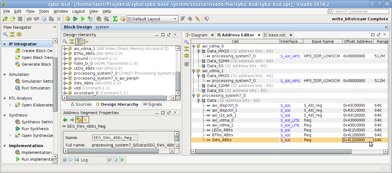
Linux provides access to the physical memory addresses via /dev/mem. It's a character device whose lower 512MB represent the physical DDR RAM present on the board. Peripherial devices are accessible via memory ranges predefined in the bitstream using memory mapped input/output. The ZYBO base system Vivado project contains following setup:

Address editor
To blink the LED-s on the board you can just grab the LEDs_4bits Offset Address from the Address Editor and using mmap() you can write and read that memory range as if it was regular array using following Python snippet.
from time import sleep
import mmap

with open("/dev/mem", "r+b") as f:
    mm = mmap.mmap(f.fileno(), 4, offset=0x41210000)
    while True:
        try:
            mm[0] = chr(0xff)
            sleep(0.2)
            mm[0] = chr(0x00)
            sleep(0.2)
        except KeyboardInterrupt:
            break
    mm.close()
Just dump the contents to a file and invoke with python at command-line.
In the source tree you'll find base.xdc which contains pin mapping for button block, switch block, LED block onboard and other preconfigured ports:
# Button block
set_property PACKAGE_PIN R18 [get_ports {btns_4bits_tri_i[0]}]
set_property PACKAGE_PIN P16 [get_ports {btns_4bits_tri_i[1]}]
set_property PACKAGE_PIN V16 [get_ports {btns_4bits_tri_i[2]}]
set_property PACKAGE_PIN Y16 [get_ports {btns_4bits_tri_i[3]}]
set_property IOSTANDARD LVCMOS33 [get_ports {btns_4bits_tri_i[*]}]

# LED block
set_property PACKAGE_PIN M14 [get_ports {leds_4bits_tri_o[0]}]
set_property PACKAGE_PIN M15 [get_ports {leds_4bits_tri_o[1]}]
set_property PACKAGE_PIN G14 [get_ports {leds_4bits_tri_o[2]}]
set_property PACKAGE_PIN D18 [get_ports {leds_4bits_tri_o[3]}]
set_property IOSTANDARD LVCMOS33 [get_ports {leds_4bits_tri_o[*]}]

# Switch block
set_property PACKAGE_PIN G15 [get_ports {sws_4bits_tri_i[0]}]
set_property PACKAGE_PIN P15 [get_ports {sws_4bits_tri_i[1]}]
set_property PACKAGE_PIN W13 [get_ports {sws_4bits_tri_i[2]}]
set_property PACKAGE_PIN T16 [get_ports {sws_4bits_tri_i[3]}]
set_property IOSTANDARD LVCMOS33 [get_ports {sws_4bits_tri_i[*]}]
Pmod connectors on the board are not by default connected to any ports. In addition to attaching port in the high level block design constraints have to be added for the corresponding pins. On the wide side ZYBO has standard Pmod connector JE connected via built-in 200Ω resistors and three hi-speed Pmod connectors JD, JC, JB with no resistors 7:
Two leftmost Pmod connectors JE, JD on the wider edge of ZYBO
Two rightmost Pmod connectors JC, JB on the wider edge of ZYBO
Pin mappings for other ports can be found in ZYBO reference manual 7 and they're virtually impossible to locate simply by searching the Internet.