Decimal counter on ZYBO05. Oct '14
Introduction
In this article I'll attempt to outline steps needed to convert VHDL design into a usable application on ZYBO board. I am going to assume that person attempting to follow the guide has familiarized herself with ZYBO basics and is using ZYBO Base System Design as starting point for the high level block design.
Sample files
In this case we're connecting two segment displays to Pmod connectors and use programmable fabric to convert bus frequency to seconds shown on the segment display:
library ieee;
use ieee.std_logic_1164.all;

entity frequency_divider is
    generic (
        RATIO : integer := 50000000);
    port (
        clk_in  : in  std_logic;
        reset   : in  std_logic;
        clk_out : out std_logic);
end;

architecture behavioral of frequency_divider is
    signal temporal: std_logic;
    signal counter : integer range 0 to RATIO := 0;
begin
    frequency_divider_process: process (reset, clk_in) begin
        if (reset = '1') then
            temporal <= '0';
            counter <= 0;
        elsif rising_edge(clk_in) then
            if (counter = RATIO) then
                temporal <= not(temporal);
                counter <= 0;
            else
                counter <= counter + 1;
            end if;
        end if;
    end process;
    clk_out <= temporal;
end;
BCD counter counts up to 10 and then overflows 2:
library ieee;
use ieee.std_logic_1164.all;
use ieee.numeric_std.all;

entity bcd_counter is
    port (
        clk_in  : in  std_logic;
        reset   : in  std_logic;
        inc     : in  std_logic;
        bcd     : out std_logic_vector(3 downto 0);
        clk_out : out std_logic);
end;

architecture behavioral of bcd_counter is
    signal temporal: std_logic;
    signal counter : integer range 0 to 10;
begin
    counter_process: process (reset, clk_in) begin
        if (reset = '1') then
            temporal <= '0';
            counter <= 0;
        elsif rising_edge(clk_in) then
            if inc = '1' then
                if (counter = 9) then
                    temporal <= '1';
                    counter <= 0;
                else
                    temporal <= '0';
                    counter <= counter + 1;
                end if;
            else
                if (counter = 0) then
                    temporal <= '1';
                    counter <= 9;
                else
                    temporal <= '0';
                    counter <= counter - 1;
                end if;
            end if;
        end if;
    end process;

    clk_out <= temporal;
    bcd <= std_logic_vector(to_unsigned(counter,4));
end;
Segment driver decodes BCD signal to segment display lanes:
library ieee;
use ieee.std_logic_1164.all;


entity bcd_segment_driver is
    port (
        bcd      : in  std_logic_vector(3 downto 0);
        segments : out std_logic_vector(6 downto 0));
end;

architecture behavioral of bcd_segment_driver is
begin
    segments <=
        "1111110" when bcd = "0000" else -- 0
        "0110000" when bcd = "0001" else -- 1
        "1101101" when bcd = "0010" else -- 2
        "1111001" when bcd = "0011" else -- 3
        "0110011" when bcd = "0100" else -- 4
        "1011011" when bcd = "0101" else -- 5
        "1011111" when bcd = "0110" else -- 6
        "1110000" when bcd = "0111" else -- 7
        "1111111" when bcd = "1000" else -- 8
        "1111011" when bcd = "1001" else -- 9
        "0000000";
end;
These files should be added by:
Open Tools → Create and Package IP
Select Package your current project
Point IP location to the folder containing these three files
Click Next
Click Finish
IP editor window should be opened now
Make adjustments to the VHDL code if necessary
Under Package IP tab open Review and Pacakage step, click Package IP button
Block design
In the Vivado high level block design window click Add IP, search for the IP core that was added and double click on it. Apply the same for remaining blocks. Use block design editor to combine frequency divider, BCD counter and BCD segment drivers:
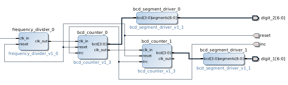
Frequency divider is connected to the ZYBO bus clocked at 50MHz
Pin mapping
Each ZYBO Pmod connector is basically connected to 8-bit port of programmable fabric. Each port's 1st pin is marked with square and pins 1-4 are in the top row and pins 5-8 are in the row closer to the PCB. Remaining four pins are connected to 3.3V and ground rails and they're explicitly marked on the board.
Pin mapping is described in ZYBO reference manual PDF documentation 1. Edit Constraints → constrs_1 → base.xdc to reflect your setup:
# Connect BTN0 to reset line
set_property PACKAGE_PIN R18 [get_ports {reset}]
set_property IOSTANDARD LVCMOS33 [get_ports {reset}]

# Pmod connector JB
set_property PACKAGE_PIN T20 [get_ports {digit_2[0]}]
set_property PACKAGE_PIN U20 [get_ports {digit_2[1]}]
set_property PACKAGE_PIN V20 [get_ports {digit_2[2]}]
set_property PACKAGE_PIN W20 [get_ports {digit_2[3]}]
set_property PACKAGE_PIN Y18 [get_ports {digit_2[4]}]
set_property PACKAGE_PIN Y19 [get_ports {digit_2[5]}]
set_property PACKAGE_PIN W18 [get_ports {digit_2[6]}]
set_property IOSTANDARD LVCMOS33 [get_ports {digit_2[*]}]

# Pmod connector JC
set_property PACKAGE_PIN V15 [get_ports {digit_1[0]}]
set_property PACKAGE_PIN W15 [get_ports {digit_1[1]}]
set_property PACKAGE_PIN T11 [get_ports {digit_1[2]}]
set_property PACKAGE_PIN T10 [get_ports {digit_1[3]}]
set_property PACKAGE_PIN W14 [get_ports {digit_1[4]}]
set_property PACKAGE_PIN Y14 [get_ports {digit_1[5]}]
set_property PACKAGE_PIN T12 [get_ports {digit_1[6]}]
set_property IOSTANDARD LVCMOS33 [get_ports {digit_1[*]}]

# Connect SW0 to increment/decrement toggle
set_property PACKAGE_PIN G15 [get_ports {inc}]
set_property IOSTANDARD LVCMOS33 [get_ports {inc}]
Final steps
Press Generate Bitstream in the left-hand panel under Program and Debug, the file will be written to zybo_base_system/source/vivado/hw/zybo_bsd/zybo_bsd.runs/impl_1/system_wrapper.bit. Transfer the file to the first FAT32 partition of the microSD card and reset the device.
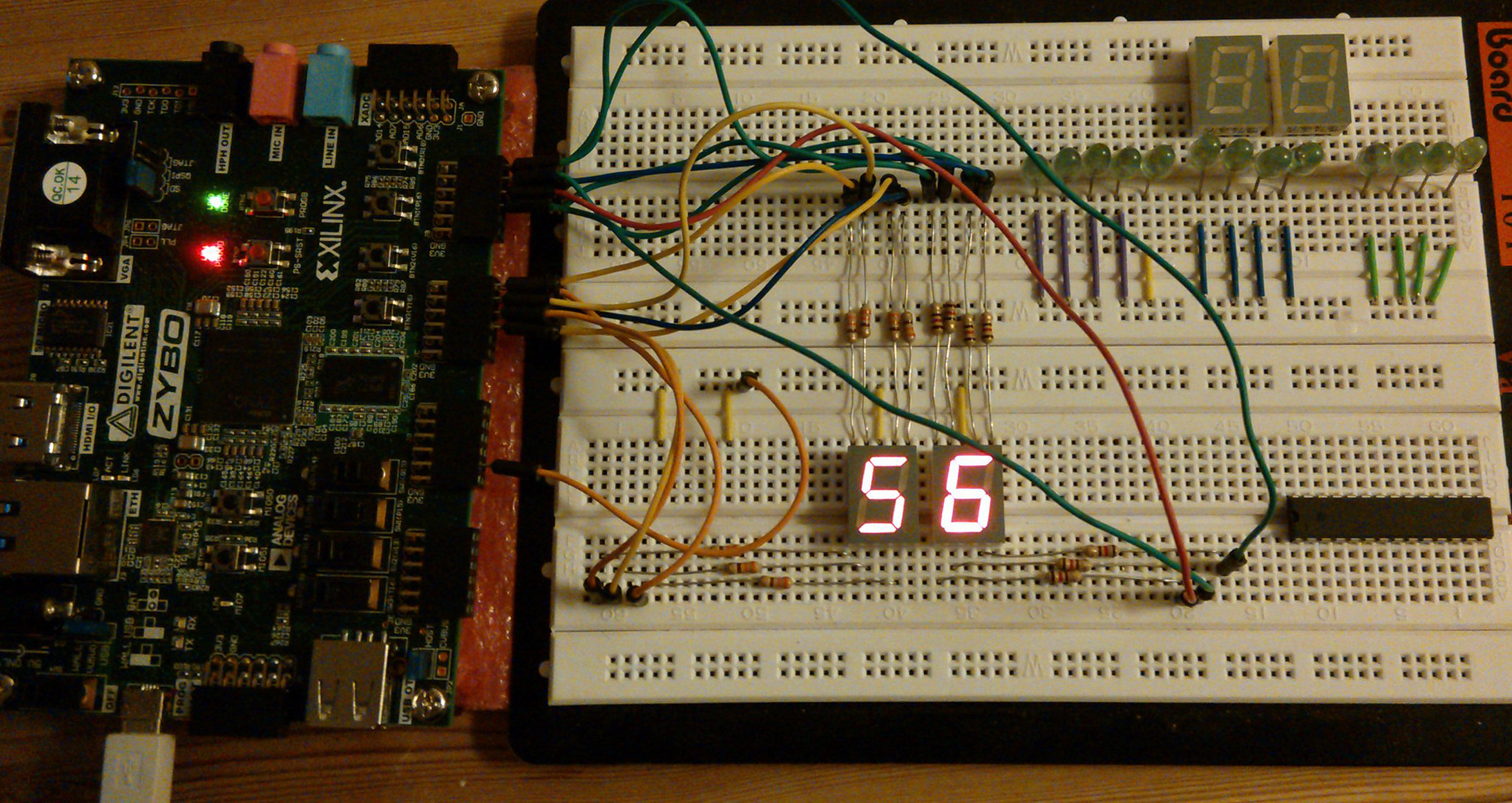
ZYBO in action