Espressif WiSoC-s10. Jun '17
Wireless System on Chip
ESP8266 is a WiSoC running a custom 32bit RISC CPU core clocked at 80MHz with 64KiB of RAM for instructions and 96KiB for data.
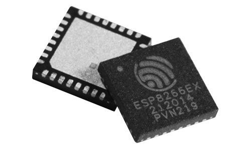
ESP8266 is just the integrated circuit that incorporates CPU and wireless into one chip
ESP32 is ESP8266 successor running at 160MHz, includes 520KiB SRAM.
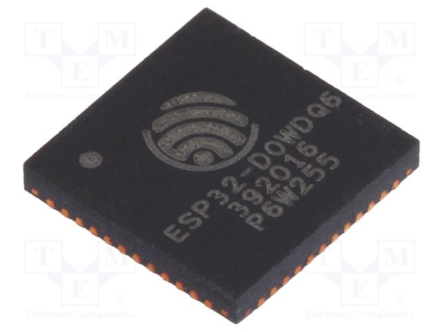
ESP32 is also just an integrated circuit
Both of them are basis for series of interesting SoM-s and development boards.
System on Module
ESP-01 incorporates ESP8266 with 1MiB (8MBit) SPI Flash and PCB antenna. It's sold at around 1.5 USD on AliExpress. On ESP-01 two GPIO-s are available (numbered 0 and 2). When more pins are needed it's possible to make use of UART pins (numbered 1 and 3). Note that PWM is available only on pins 0 and 2.
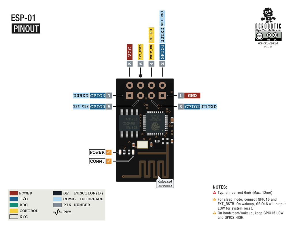
ESP-01 uses ESP8266
ESP32 in very often packaged as ESP-WROOM-32 which includes 4MiB (32MBit) of SPI Flash and it's sold at Aliexpress for 4 USD.
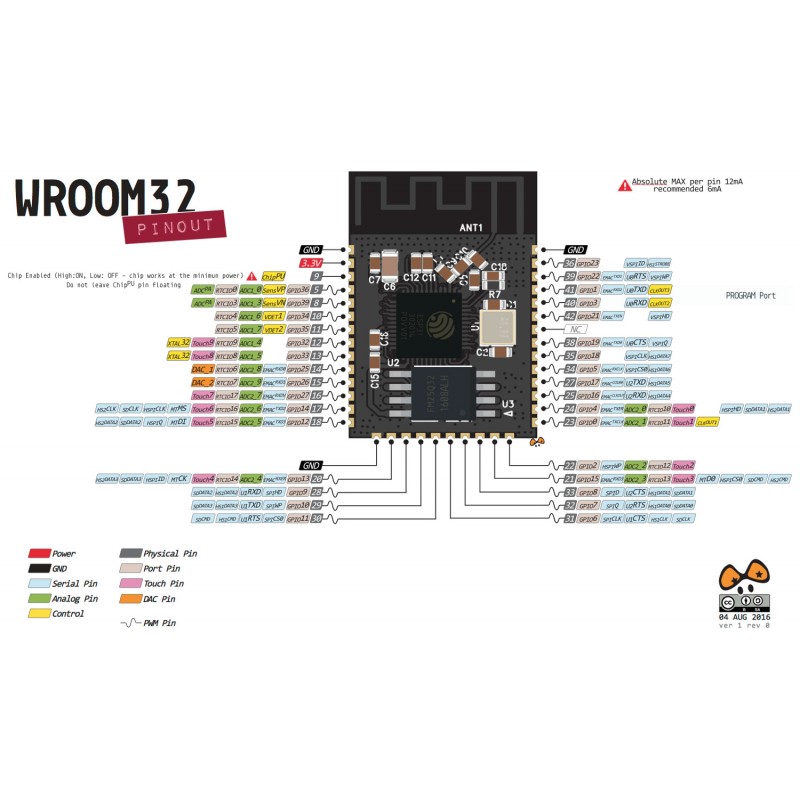
ESP-WROOM-32 is based on ESP32, but it's usually shielded so no guts are visible
Development boards
Both ESP8266 and ESP32 have development boards available for around 10 USD. There are open source GCC toolchains and are suitable for building IoT devices.
NodeMCU is based on ESP-12 SOM and includes USB-UART bridge, 3.3V voltage regulator and PCB antenna
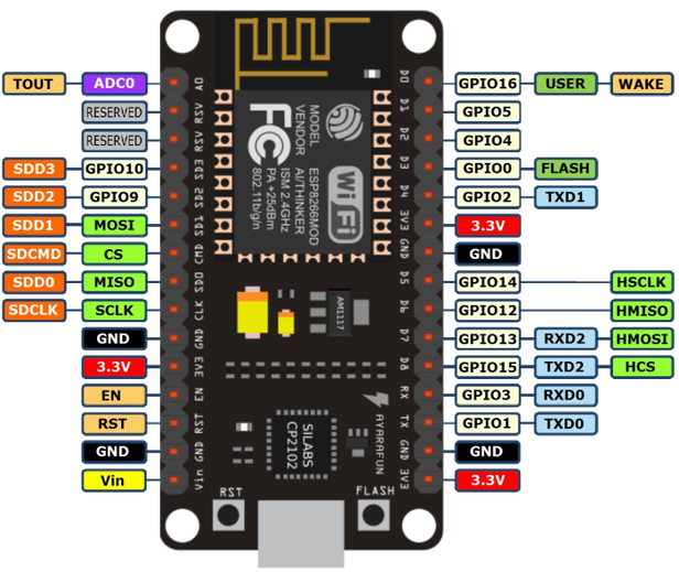
NodeMCU
WeMos Lolin32 uses ESP-WROOM-32, includes LiPo charging circuit, voltage regulators and USB-UART bridge:
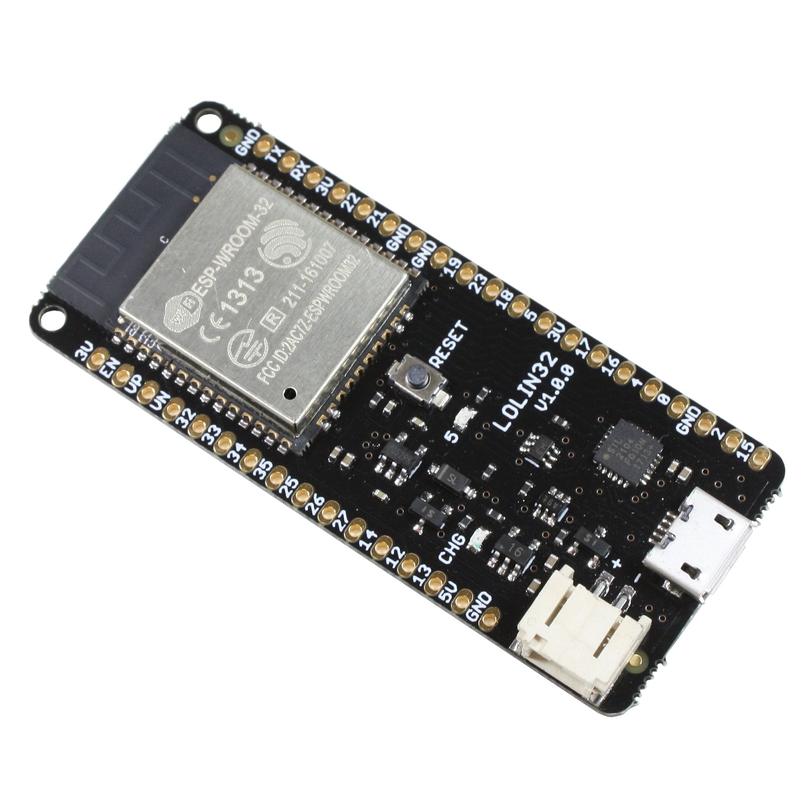
WeMos Lolin32
Note that board pin numbering rarely matches ESP-s pin numbering:
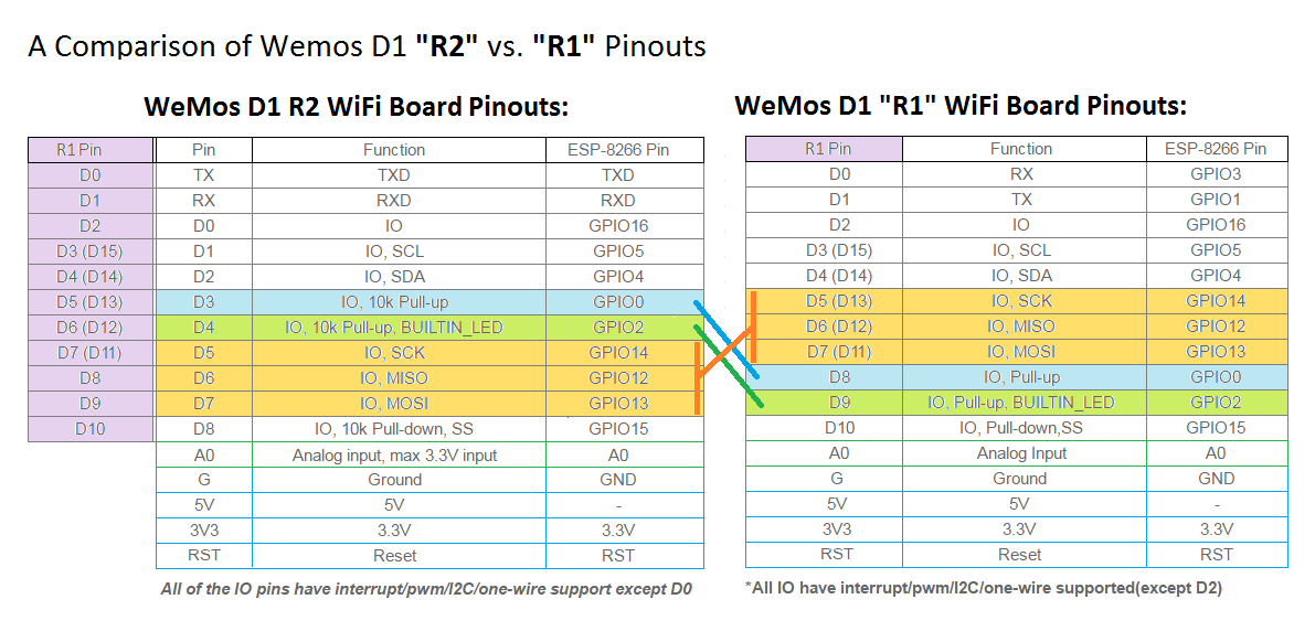
WeMos D1 R1 vs R2
Even different revisions of the same board model have different pin mappings.
Flashing MicroPython
MicroPython is Python 3 for microcontrollers that runs on bare metal (no OS) and it implements a subset of the standard library. It was originally developed for STM32F405RG microcontroller, but later ported to others including ESP8266 and now ESP32 as well.
First install esptool, note that you need to upgrade to 2.x for ESP32 support:
pip install esptoolTo install on ESP8266 based boards:
wget http://micropython.org/resources/firmware/esp8266-20170612-v1.9.1.bin
esptool.py -p /dev/ttyUSB0 -b 460800 erase_flash
esptool.py -p /dev/ttyUSB0 -b 460800 write_flash 0 esp8266-*.bin
To install on ESP32 based boards:
wget http://micropython.org/resources/firmware/esp32-20171206-v1.9.2-445-g84035f0f.bin
esptool.py -p /dev/ttyUSB0 -b 460800 erase_flash
esptool.py -p /dev/ttyUSB0 -b 460800 write_flash --flash_mode dio 0x1000 esp32-*.bin
Important
If your board doesn't have integrated USB-UART bridge, eg in case of ESP-01 you need a USB-UART bridge and to manually ground pin 0 to enable programming mode
Connecting to MicroPython prompt
First use following to open up Python prompt from the device, note that you can exit picocom by pressing Ctrl-A followed by Ctrl-Q:
picocom -b115200 /dev/ttyUSB0First step is to press enter to see that Python interpreter is running, it should return >>> which is the indicator for Python prompt.
Next you can check what Python version is running:
import sys
sys.version # This should return 3.4.0 at the moment
To connect to wireless network, synchronize time and start web command prompt server paste following statements to the Python prompt:
# Connect to wireless network as client
import network
wlan = network.WLAN(network.STA_IF)
wlan.active(True)
wlan.connect("itcollege")

# Synchronize clock
import ntptime
ntptime.settime()

# Create a variable for hostname based on MAC address:
import ubinascii as binascii
name = "esp-%s" % binascii.hexlify(wlan.config("mac")[-3:]).decode("ascii")

# Clean up
import gc
gc.collect()
Save the same snippet into boot.py and then use either REPL over UART or WebREPL client upload the boot.py file. Note that you have to disconnect picocom to use REPL over UART.
pip install adafruit-ampy # Install Adafruit MicroPython Tool
ampy -p /dev/ttyUSB0 put boot.py # Upload boot.py over UART
Next reboot the script will be automatically executed and you'll have persistent connection to your wireless network.
Storage
MicroPython partitions the SPI Flash so the unused space is formatted as FAT filesystem and exposed over Python's filesystem interfaces. You can use WebREPL or REPL to list and upload files from your PC. Within Micropython you can use os.listdir to list files and open to manipulate file contents.
import os
block_size, _, blocks, blocks_free, _, _, _, _, _, _ = os.statvfs("")
print("Filesystem size: %d KiB" % (blocks * block_size >> 10))
print("Free space: %d KiB" %  (blocks * blocks_free >> 10))
You should have couple hundred kilobytes free space for configuration files and some media files.
Blinking LED-s
Machine specific interfaces are grouped to module machine at least on ESP8266 and ESP32. To blink on-board LED-s on WeMos D1:
# WeMos D1
from time import sleep
from machine import Pin
som_led = Pin(2, mode=Pin.OUT)    # D9 on Wemos D1, LED on the SOM
sck_led = Pin(14, mode=Pin.OUT)   # D13 on Wemos D1, LED connected to SCK
for i in range(0,10):
    som_led.value(0) # Polarity inverted, pin sinks 3.3v
    sck_led.value(1) # Pin sources voltage
    sleep(0.2)
    som_led.value(1)
    sck_led.value(0)
    sleep(0.2)
Even ESP-01 has a LED hooked to serial transmit pin:
# ESP-01
from time import sleep
from machine import Pin, reset
tx = Pin(1, mode=Pin.OUT)
for i in range(0,10):
    tx.value(0) # Polarity inverted, pin sinks 3.3v
    sleep(0.2)
    tx.value(1)
    sleep(0.2)
reset() # UART transmit pin is dead by now, reset device to restore serial
Reading pins
In this case an external push button is connected to D8 on WeMos D1, note that you can just use a jumper cable hanging freely and to simulate a button press the other end is just clicked against the USB port shielding (the ground).
from machine import Pin
from time import sleep
pin_led = Pin(14, mode=Pin.OUT)    # D13 on Wemos D1, on-board LED connected (SCK)
pin_button =  Pin(0, mode=Pin.IN)  # D8 on Wemos D1
turned_on = False
while True:
    if not pin_button.value():
        turned_on = not turned_on
    pin_led.value(turned_on)
    sleep(0.01) # Sleep for 10ms
For other pins which dont have pull up resistors on-board an internal pull up resistor (fused into the integrated circuit) may be used:
pin = machine.Pin(0, machine.Pin.IN, machine.Pin.PULL_UP)Note that on Wemos D1 pin 0 (D8) is connected via pull up to 3.3v rail to prevent accidental boots into flashing mode. This also keeps the voltage level high on the pin 0 (D8) if the wire is freely hanging.
Using hardware interrupts
Interrupts allow CPU to sleep for most time, in following example LED is toggled when button is released.
from machine import Pin
from time import sleep

pin_led = Pin(14, mode=Pin.OUT)    # D13 on Wemos D1, on-board LED connected (SCK)
pin_button =  Pin(0, mode=Pin.IN)  # D8 on Wemos D1
turned_on = False

def callback(p):
    global turned_on
    turned_on = not turned_on
    pin_led(turned_on)

pin_button.irq(trigger=Pin.IRQ_FALLING, handler=callback)
Note that most buttons don't have very realiable mechanics giving you several falling edge events during button press. Use capacitor on the switch pin to have more reliable operation or add code for debounce.
Using timers
Timers are sort of like interrupts but instead of being triggered by a pin, they're triggered after certain amount of time.
from machine import Pin, Timer
from time import sleep

pin_led = Pin(14, mode=Pin.OUT)    # D13 on Wemos D1, on-board LED connected (SCK)
pin_button =  Pin(0, mode=Pin.IN)  # D8 on Wemos D1
timer = Timer(-1)

def timeout_callback(t):
    pin_led(0)

def button_callback(p):
    pin_led(1)
    timer.init(period=1000, mode=Timer.ONE_SHOT, callback=timeout_callback)

pin_button.irq(trigger=Pin.IRQ_FALLING, handler=button_callback)
Timer that executes callback repeatedly can be initialized with mode=Timer.PERIODIC.
Dimming LED-s
Both ESP-s have hardware PWM generators which means you can get accurately timed squarewave signals which can be used to dim LED-s or drive motors.
# NodeMCU
from time import sleep_ms
from machine import Pin, PWM
led = PWM(Pin(2, Pin.OUT), freq=400) # Initialize at 400Hz

for j in range(0,10):
    for i in range(1023,-1,-10):
        led.duty(i)
        sleep_ms(5)
    for i in range(0, 1024, 10):
        led.duty(i)
        sleep_ms(2)
Creating a webserver
MicroPython doesn't come with HTTP server wrapper classes, but you can use Berkeley sockets style programming interfaces out of the box:
import socket
from machine import Pin

led_pin = Pin(5, Pin.OUT)

CONTENT = """\
HTTP/1.0 200 OK
Content-Type: text/html

<html>
  <head>
  </head>
  <body>
    <p>Hello #%d from MicroPython!</p>
    <a href="/toggle">Click here to toggle LED hooked to pin 5</a>
  </body>
</html>
"""

def main():
    s = socket.socket()
    ai = socket.getaddrinfo("0.0.0.0", 8080)
    print("Bind address info:", ai)
    addr = ai[0][-1]

    s.setsockopt(socket.SOL_SOCKET, socket.SO_REUSEADDR, 1)
    s.bind(addr)
    s.listen(5)
    print("Listening, connect your browser to http://<this_host>:8080/")

    counter = 0
    while True:
        sock, addr = s.accept()
        print("Client address:", addr)
        stream = sock.makefile("rwb")
        req = stream.readline().decode("ascii")
        method, path, protocol = req.split(" ")
        print("Got", method, "request for", path)
        if path == "/toggle":
            led_pin.value(1-led_pin.value())
        while True:
            h = stream.readline().decode("ascii").strip()
            if h == "":
                break
            print("Got HTTP header:", h)
        stream.write((CONTENT % counter).encode("ascii"))
        stream.close()
        sock.close()
        counter += 1
        print()

main() # Press Ctrl-C to stop web server
WebSockets
MicroPython has BSD sockets style API for IP-based networks. For high level protocols such as HTTP and WebSockets modules are popping up.
In this example ESP is connected nchan enabled nginx web server. The configuration of nginx/nchan looks something like this. This configuration basically allows broadcasting messages between nodes connected to same nginx server even if the nodes are behind NAT or firewall:
server {
    listen 80;
    server_name iot.koodur.com;
    root /var/www/iot;
    location ~ "^/ws/(.*?)" {
        nchan_channel_id $1;
        nchan_pubsub websocket;
        nchan_message_buffer_length 0;
    }
}
Pull a Python module for creating websockets and upload it to ESP:
wget https://gist.githubusercontent.com/laurivosandi/2983fe38ad7aff85a5e3b86be8f00718/raw/cfa52f739080d42029d21017c5ae2a7b97793b06/uwebsockets.py
ampy -p /dev/ttyUSB0 put uwebsockets.py
Example code for ESP:
import sys
import uwebsockets
from machine import Pin, PWM
led = PWM(Pin(14, mode=Pin.OUT), freq=400) # SCK LED on WeMos D1
uri = "ws://iot.koodur.com:80/ws/living-room-of-lauri"
print("Connecting to:", uri)
conn = uwebsockets.connect(uri)
conn.send("alive")
while True:
    print("Reading message...")
    try:
        fin, opcode, data = conn.read_frame()
    except OSError: # Connection timeout or reset
        sys.exit() # Soft reset
    if data.startswith(b"duty:"):
        led.duty(int(data[5:]))
    else:
        print("Got unknown command:", data)
Relevant code for the web:
<!DOCTYPE html>
<html>
<head>
  <script type="text/javascript">
  var ws = new WebSocket("ws://iot.koodur.com:80/ws/living-room-of-lauri/");
  ws.onopen = function (event) { console.info("websocket connected"); };
  ws.onmessage = function (event) { console.log(event.data); }
  var lastValue = false;
  function duty(e) {
    if (lastValue == e.value) return;
    lastValue = e.value;
    ws.send("duty:" + e.value);
  }
  </script>
</head>
<body>
  <input type="range" min="0" max="1023" step="10" onMouseMove="duty(this);" onTouchMove="duty(this);"/>
</body>
</html>
Important
Replace living-room-of-lauri with an unique string, otherwise you'll end up flicking switch in my living room
Unicast WebSockets
In the example above the messages are broadcasted to all nodes connected to the same WebSockets URI, including the message publisher itself. For IoT lamp this is great, all lamps get the message and browsers as well - this helps keeping things in sync.
If you want to have sort of unicast communications between two nodes, you can try following nchan config:
server {
    listen 80;
    server_name iot.koodur.com;
    root /var/www/iot;
    location ~ "^/p2p/([\w\d\-]+)/([\w\d\-]+)" {
        nchan_pubsub websocket;
        nchan_message_buffer_length 0;
        nchan_publisher_channel_id $1/$2;
        nchan_subscriber_channel_id $2/$1;
    }
}
On the ESP end use:
uri = "ws://iot.koodur.com:80/p2p/lamp-123456/browser/"On the browser end use:
var ws = new WebSocket("ws://iot.koodur.com:80/p2p/browser/lamp-123456/");This config shall prevent echoing messages to publisher as well.
Driving SSD1306 OLED screens
Python module for driving such OLED screens can be pulled from MicroPython's Git repo:
wget https://raw.githubusercontent.com/micropython/micropython/master/drivers/display/ssd1306.py
ampy -p /dev/ttyUSB0 put ssd1306.py
Random ESP32 based board with a screen from AliExpress used I2C interface but the chip also supports SPI interace. In this case the I2C interace is bit banged on pins 4 and 5.
To paste chunks of indented text like the one below press Ctrl-E, paste the text as usual by right clicking in the terminal and selecting Paste. Once finished press Ctrl-D to tell Python interpreter that you're done.
from time import sleep_ms
from machine import Pin, I2C
from ssd1306 import SSD1306_I2C

i2c = I2C(-1, Pin(4),Pin(5),freq=400000) # Bitbanged I2C bus
assert 60 in i2c.scan(), "No OLED display detected!"
oled = SSD1306_I2C(128, 64, i2c)
buf = "wubba lubba dub dub  "
oled.invert(0) # White text on black background
oled.contrast(255) # Maximum contrast
j = 0

while True:
    oled.fill(0)
    oled.text(buf[j%len(buf):]+buf, 10, 10)
    oled.show()
    sleep_ms(20)
    j += 1
And it works!
Text scrolling on SSD1306 based OLED screen hooked to ESP32
Powering
According to datasheet ESP32 can be powered with 2.3V to 3.6V power source, but fiddling around with bench power supply the basic functionality seemed to be intact even with voltages from 2V to 4V drawing constantly 60mA. Below 2V or over 4V the ESP32 cuts it's power consumption.
Summary
ESP8266 is just enough to build WiFi connected LED lights or a Nixie clock. ESP32 is a bit beefier and suitable for building a sumorobot. Schematics and up to date code of MicroPython based, NTP-synchronized and IN-12 based Nixie clock can be found at GitHub.